Pipe Welding Consumable Calculator
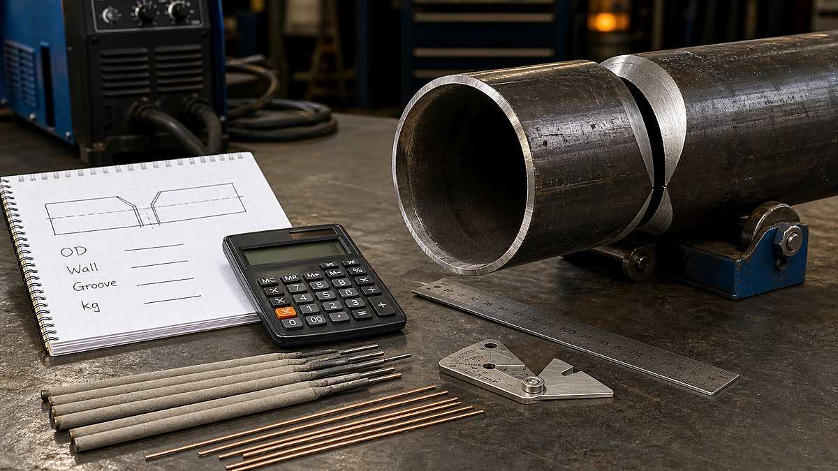
A pipe welding consumable calculator estimates how much electrode, wire, or filler rod is needed for one pipe joint or a complete piping job. The estimate starts with pipe outside diameter and weld-joint geometry, converts the groove into deposited weld-metal weight, then adjusts for deposition efficiency and purchasing allowance.
Pipe estimates need more detail than a simple weld-length calculation. Wall thickness, bevel angle, root opening, root face, cap reinforcement, joint count, material density, and the process used for the root, fill, and cap can all change the answer. A six-inch pipe description alone is not enough.
Mark Dawson beginner note: use the calculator for planning and ordering, not for designing the joint. Pipe weld preparation, filler classification, pass sequence, preheat, inspection, and acceptance requirements must come from the drawing, welding procedure, code, and qualified personnel.
Quick Pipe Consumable Formula
The calculation follows five steps:
- Calculate pipe circumference from the actual outside diameter.
- Estimate the filled cross-sectional area of the groove.
- Multiply area by circumference and joint quantity to get weld volume.
- Multiply volume by filler-metal density to get deposited weight.
- Divide by deposition efficiency and add a visible purchasing allowance.
The core equations are:
- Circumference = π × pipe OD
- Weld volume = groove area × circumference × number of joints
- Deposited weight = weld volume × metal density
- Consumable used = deposited weight ÷ deposition efficiency
- Purchase quantity = consumable used × (1 + allowance)
Keep all dimensions in one unit system. If area is in mm² and length is in mm, volume is in mm³. For steel with density near 7.85 g/cm³, the metric weight equation is:
Deposited steel weight in kg = volume in mm³ × 7.85 ÷ 1,000,000
Inputs the Calculator Needs
| Input | Use | Common Error |
|---|---|---|
| Actual pipe OD | Calculates girth-weld length | Using nominal pipe size as OD |
| Wall thickness | Sets groove depth | Guessing from pipe diameter |
| Included groove angle | Controls bevel volume | Using per-side angle as included angle |
| Root opening | Adds fill volume through the joint | Leaving it out of the estimate |
| Root face | Changes beveled depth | Assuming the full wall is beveled |
| Cap allowance | Adds reinforcement above the pipe surface | Counting groove volume only |
| Joint quantity | Scales one joint to the job | Missing field-fit or repair joints |
| Process efficiency | Converts deposit to purchased filler | Assuming 100% deposition |
Use the OD and wall thickness from the pipe specification, drawing, or verified measurement. Nominal pipe size is a naming system; it is not always the measured outside diameter. Schedule also does not mean one universal wall thickness across every nominal size.
Estimate Pipe Circumference
A circumferential butt weld follows the outside of the pipe. For one complete girth joint:
Girth-weld length = π × outside diameter
A pipe with an actual OD of 168.3 mm has a circumference of approximately 528.7 mm. Ten identical joints provide 5,287 mm, or about 5.29 meters, of girth-weld length. This does not mean one pass; a multi-pass joint places several beads around the same circumference.
Branch connections, socket welds, reinforcement pads, and flange fillets use different weld paths and geometry. Calculate those as separate line items. The Fillet Weld Size Calculator is a better starting point for equal-leg fillet geometry.
Approximate a Single-V Groove Area
For a simplified symmetrical single-V pipe joint, define:
- t = wall thickness
- f = root face
- b = beveled depth, calculated as t − f
- g = root opening
- θ = included groove angle
- Acap = estimated cap and reinforcement area
A transparent planning approximation is:
Groove area ≈ (g × t) + [b² × tan(θ ÷ 2)] + Acap
The root-gap term estimates the space between the pipe ends. The bevel term represents the two side triangles together. The cap term accounts for reinforcement above the theoretical groove. This is not a universal joint-design equation. Internal mismatch, backing, land shape, penetration profile, counterbore, compound bevels, and actual bead contour can change the filled area.
For accurate code work, use the approved joint detail or calculate area from a scaled cross-section. A macro section from a qualified test weld can also provide better production data than a generic geometric assumption.
Worked Example: 168.3 mm OD Steel Pipe
Assume one carbon-steel pipe joint with these planning inputs:
| Input | Value |
|---|---|
| Outside diameter | 168.3 mm |
| Wall thickness | 7.11 mm |
| Root face | 1.6 mm |
| Root opening | 3.0 mm |
| Included angle | 60° |
| Cap allowance area | 20 mm² |
| Steel density | 7.85 g/cm³ |
Beveled depth is 7.11 − 1.6 = 5.51 mm. The root-gap area is 3 × 7.11 = 21.33 mm². The bevel area is 5.51² × tan 30°, or about 17.53 mm². Adding 20 mm² for the cap gives an estimated cross-sectional area of 58.86 mm².
Circumference is π × 168.3 = 528.73 mm. Estimated volume is 58.86 × 528.73 = 31,127 mm³. The deposited steel weight is approximately:
31,127 × 7.85 ÷ 1,000,000 = 0.244 kg of deposited weld metal
The result is a geometric estimate for one joint. Measure the real joint preparation and use a suitable cap-area assumption before applying it to purchasing.
Working in Inches and Pounds
The same method works in U.S. customary units. Keep groove area in square inches and circumference in inches, producing volume in cubic inches. Multiply by filler-metal density in pounds per cubic inch.
- Carbon steel planning density: about 0.283 lb/in³
- Stainless steel density: use the value for the selected alloy
- Aluminum planning density: about 0.098 lb/in³
Deposited weight in pounds = groove area in in² × circumference in inches × joint count × density in lb/in³
Do not calculate the groove in millimeters and then multiply by a density stated in lb/in³. Convert every geometric value before applying density. A useful audit is to write the unit beside every input and result rather than storing numbers without labels.
Calibrate the Estimate with a Test Joint
Geometry provides a starting point; production records make it stronger. For a representative test joint, record unopened consumable weight, issued weight, returned usable weight, discarded stubs or rod ends, and any repair consumption. Compare net issued consumable with the calculator result.
If ten repeat joints used 4.2 kg while the calculator predicted 3.8 kg, investigate before changing the factor. The difference may come from a larger cap, joint mismatch, a wider root opening, repair welding, conservative technique, or package-handling loss. Correct the input that caused the difference instead of adding an unexplained multiplier.
Keep separate history for shop and field work, and for each process combination. A TIG-root/SMAW-fill joint should not inherit the same factor as an all-GMAW shop joint. After several jobs, the comparison provides a realistic purchasing allowance while the approved joint geometry and procedure remain unchanged.
Apply Deposition Efficiency
Deposition efficiency is the portion of consumed filler that becomes weld metal. The rest may be lost through stick-electrode stubs, spatter, slag-related loss, wire clipping, fumes, or unusable rod ends. Use manufacturer or shop data when available.
| Process | Planning Range | Main Losses |
|---|---|---|
| SMAW / stick | About 55-70% | Stub ends, slag, spatter, restarts |
| GMAW / solid MIG | About 85-95% | Spatter, wire clipping, setup waste |
| FCAW | About 75-90% | Slag, spatter, wire and setup losses |
| GTAW / TIG filler | Often high but job-dependent | Cut ends, contamination, unused rod |
| SAW | Often high in controlled work | Start/stop and wire losses |
These are planning ranges, not procedure values. Consumable classification, transfer mode, position, settings, operator technique, and repair rate affect the actual number. The Advanced Weld Consumable Calculator explains the broader volume-to-purchase workflow.
Mixed-Process Root, Fill, and Cap
Many pipe joints use one process for the root and another for fill and cap. Do not apply one average efficiency without showing the assumption. Split the deposited weight by pass group, then calculate each consumable separately.
Suppose the worked example assigns 15% of deposited metal to a TIG root and hot pass, with the remaining 85% deposited by stick electrodes. Using 95% planning efficiency for TIG and 65% for stick:
- TIG deposit: 0.244 × 0.15 = 0.0366 kg
- TIG filler used: 0.0366 ÷ 0.95 = 0.0385 kg
- Stick deposit: 0.244 × 0.85 = 0.2074 kg
- Stick electrodes used: 0.2074 ÷ 0.65 = 0.3191 kg
- Combined filler before allowance: about 0.358 kg per joint
With a separate 10% purchasing allowance, the estimate becomes approximately 0.394 kg per joint. For 24 similar joints, the calculated purchase requirement is about 9.46 kg before rounding to available rod and filler packages.
Estimate Stick Electrode Packages
Stick electrodes are normally purchased by package weight. The safest procurement method is to estimate kilograms or pounds of electrode, then round up to sealed package sizes while respecting storage requirements. Counting rods from core-wire geometry can be misleading because coating weight, rod length, stub length, and manufacturer construction vary.
If a manufacturer provides electrodes per kilogram or deposited metal per electrode, use that product-specific value. Keep root electrodes and fill/cap electrodes separate when classifications or diameters differ. Review Welding Rod Specifications before treating two electrode labels as interchangeable.
Low-hydrogen electrode ordering should also consider unopened package sizes, oven capacity, exposure limits, and rebaking rules. Material that cannot be stored correctly is not useful backup stock.
Estimate MIG, Flux Core, or TIG Filler
Continuous wire is bought by spool or drum weight. Once purchased weight is known, round to a package compatible with the feeder. Wire diameter changes feed speed and deposition rate, but it does not change the amount of deposited metal required by the groove. It changes how that metal is delivered.
TIG filler can be planned by weight or by product packages. Diameter and cut length matter when estimating pieces, but actual use depends heavily on root gap, feeding technique, and how much rod becomes an unusable short end. Compare common diameters in the Welding Wire Size Chart.
Add Shielding Gas Separately
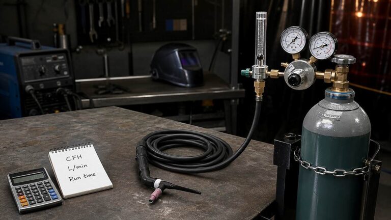
Filler-metal weight does not directly provide shielding-gas volume. Estimate arc time from deposited weight and a realistic deposition rate, then add pre-flow, post-flow, purge time, and a leak or setup allowance.
Arc time = deposited weight ÷ deposition rate
Shielding gas = flow rate × total gas-on time
Pipe purging may use more gas than the torch, especially during initial displacement and waiting for an acceptable oxygen level. Keep purge gas as its own line item. Use the Gas Flow Rate Calculator and Formula for CFH, L/min, runtime, and cost conversions.
Allow for Field Conditions and Repairs
A clean repeatable shop joint may track geometry closely. Field welding can add fit-up correction, wind protection, interrupted work, damaged bevels, moisture control, access limitations, test coupons, tie-ins, and repair excavation. Keep those risks visible instead of silently increasing groove area.
A purchasing allowance is not the same as deposition efficiency. Efficiency accounts for process loss while creating acceptable weld metal. Allowance covers uncertainty, packaging, setup, and expected rework. Applying both to the same loss without explanation can double-count waste.
Calculator Verification Checklist
- Confirm actual OD and wall thickness from the correct pipe specification.
- Verify whether the groove angle is per side or included.
- Use the approved root opening, root face, and cap detail.
- Separate butt welds, socket welds, branches, and fillets.
- Count field welds, shop welds, tie-ins, and test welds correctly.
- Match density to carbon steel, stainless steel, nickel alloy, or aluminum.
- Split root, fill, and cap when different processes are used.
- Use documented efficiency or conservative shop data.
- Add purchasing allowance once and label it clearly.
- Round to actual package sizes and storage capacity.
Safety and Quality Limits
Pipe welds may carry pressure, hazardous material, steam, fuel, or structural load. A consumable quantity estimate cannot approve the joint, select a filler, qualify a procedure, or replace inspection. Use the applicable code, engineering requirements, WPS, welder qualification, material controls, and required NDE.
Welding involves fumes, UV radiation, hot metal, fire, electric shock, compressed gas, grinding debris, and confined-space hazards. Pipe interiors can trap gases or create oxygen-deficient conditions. Review OSHA welding hazard guidance, OSHA compressed-gas information, and AWS free safety resources. Manufacturer references such as the Kobelco welding guide can help explain consumable calculation principles, but project documents remain controlling.
FAQ
How do you calculate welding rods for a pipe joint?
Calculate groove area, multiply it by pipe circumference to get volume, convert volume to deposited weight with material density, then divide by the electrode deposition efficiency. Add a separate allowance and round to package size.
Should nominal pipe size be used as outside diameter?
No. Use the actual outside diameter from the relevant pipe specification or a verified measurement. Nominal size is a designation and may not equal OD.
Does the number of passes change total consumable weight?
The groove volume controls the base deposited weight, but extra passes can increase reinforcement, starts, stops, overlap, cleaning loss, and repair risk. Use the real pass plan and joint profile.
What deposition efficiency should I use for E7018?
Use manufacturer or measured shop data where possible. A planning estimate often treats stick welding as lower efficiency than continuous solid wire because of stub, slag, and spatter losses. Do not assume one value fits every electrode and position.
Can the calculator estimate welding time?
It can estimate arc time by dividing deposited weight by deposition rate. Total job time also needs fit-up, tacking, cleaning, repositioning, preheat, interpass control, inspection, and operator factor.
How much extra consumable should I order?
Base the allowance on package sizes, storage, job history, repair risk, field conditions, and schedule consequences. Keep it separate from deposition efficiency so the estimate remains auditable.
Final Advice
A pipe welding consumable calculator is most useful when every assumption is visible. Start with actual pipe dimensions and approved groove geometry, calculate deposited metal, split processes where needed, and apply efficiency before adding a separate purchasing allowance.
After the first production joints, compare calculated use with issued and returned consumables. That feedback turns a geometric estimate into reliable shop data without confusing purchasing quantities with weld quality requirements.