Calculate Gas Flow Rate from Pressure Measurement
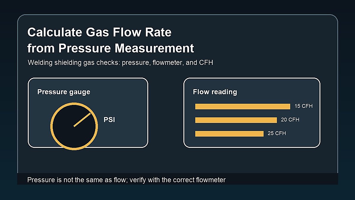
Many welders want to calculate gas flow rate from pressure measurement because the regulator has a pressure gauge, the cylinder has a pressure reading, and the weld needs a shielding gas flow in CFH or L/min. The problem is that pressure and flow are not the same measurement.
Pressure tells you how hard the gas is pushing in a cylinder, hose, regulator, or line. Flow rate tells you how much gas is moving over time. In welding, the flow number that matters at the torch or MIG gun is usually cubic feet per hour, often written as CFH, or liters per minute in metric setups.
Mark Dawson beginner note: do not set shielding gas by pressure alone. A pressure gauge can show cylinder pressure or line pressure, but a flowmeter or flow gauge is what helps you set the shielding gas that reaches the weld zone.
Quick Answer
You usually cannot calculate welding gas flow rate from pressure measurement alone. To calculate flow from pressure, you also need the orifice size, gas type, temperature, upstream and downstream pressure, regulator behavior, and whether the gas flow is restricted or choked. For normal MIG and TIG welding, use a proper flowmeter or flow gauge and set the shielding gas in CFH or L/min.
A basic welding flow check is simple: open the cylinder, set the regulator or flowmeter, trigger gas flow through the gun or torch, and read the flow while gas is moving. Do not rely on static pressure alone. Static pressure can look fine while actual nozzle flow is too low because of leaks, restrictions, wrong fittings, a clogged diffuser, or a damaged flow device.
| Measurement | What It Tells You | Common Welding Use |
|---|---|---|
| Cylinder pressure | How much pressure is in the gas cylinder | Estimate remaining gas, not nozzle flow |
| Regulator pressure | Pressure after the regulator | Line control on pressure regulators |
| Flow rate | Gas volume moving over time | Set MIG/TIG shielding gas |
| CFH | Cubic feet per hour | Common U.S. welding flow unit |
| L/min | Liters per minute | Common metric welding flow unit |
Pressure vs Flow Rate
Pressure is force per area. Flow rate is volume per time. A gas cylinder can have high pressure but no flow if the valve is closed. A hose can have pressure but weak flow if a restriction blocks the path. A single pressure reading by itself does not tell you how much shielding gas is covering the weld pool.
Think of a water hose. You can feel pressure in the hose, but the actual amount of water coming out depends on the nozzle opening, kinks, valve position, and restrictions. Shielding gas acts differently from water because it is compressible, but the beginner lesson is the same: pressure is not the same thing as flow.
For welding, the practical question is not just “what is the pressure?” It is “how much gas is actually reaching the cup or nozzle while welding?” A flowmeter reading is more useful than a pressure-only reading when setting shielding gas.
Can You Calculate Flow from Pressure?
Yes, flow can be calculated from pressure in engineering situations, but not from one pressure number alone. The calculation needs the gas path details. A small orifice at the same pressure can flow much less gas than a larger opening. A long hose, small fitting, clogged screen, or damaged regulator can change the result.
For a simple restriction, flow is related to pressure difference across the opening, gas density, and orifice area. With compressible gases, the calculation can become more complex when pressure drop is high. In normal welding setup, shops use a flowmeter calibrated for the gas and unit instead of asking beginners to derive shielding gas flow from pressure.
If a manufacturer gives a chart that converts pressure to flow for a specific regulator, torch, nozzle, or flow device, use that chart only for that exact equipment. Do not copy the chart to a different regulator or gas setup.
Basic Formula Idea
The simplified idea behind many flow calculations is:
Flow depends on opening area, pressure difference, gas density, and discharge behavior.
That sounds simple, but the missing details matter. A pressure gauge might show line pressure before the restriction, while the downstream pressure, orifice size, and discharge coefficient are unknown. Without those, the math becomes a guess.
| Needed Detail | Why It Matters | Beginner Problem |
|---|---|---|
| Orifice or opening size | Controls how much gas can pass | Usually unknown in a welding gun |
| Pressure difference | Flow depends on pressure drop, not one gauge reading | Downstream pressure may be unknown |
| Gas type | Argon, CO2, helium, and mixes behave differently | Wrong scale gives wrong reading |
| Temperature | Gas density changes with temperature | Usually ignored in shop estimates |
| Flow device calibration | Flowmeters are built for certain gases and ranges | Using the wrong flowmeter can mislead |
How Welders Should Check Gas Flow
For MIG and TIG welding, the better method is to measure or set flow while gas is moving. If your regulator has a flowmeter tube, the ball or float should be read according to the manufacturer instructions. If your setup uses a flow gauge, read the flow scale for the correct gas. Some welders also use a handheld nozzle flow tester at the MIG gun or TIG cup.
- Secure the cylinder upright before opening the valve.
- Confirm the gas label matches the process.
- Open the cylinder valve as instructed by the supplier or manufacturer.
- Trigger gas flow through the gun or torch.
- Read the flow while gas is moving, not while the system is static.
- Set flow in CFH or L/min for the process and cup or nozzle size.
- Check for leaks, loose fittings, damaged hoses, and clogged diffusers.
- Run a test bead on scrap before welding the project.
If you are planning cylinder size and run time, read Welding Tank Size Chart. If you are building a broader reference set, compare Gas Flow Rate Calculator and Formula when that calculator page is available.
Regulator, Flowmeter, and Flow Gauge Differences
A pressure regulator reduces cylinder pressure to a usable outlet pressure. A flowmeter measures or controls volume moving over time. A flow gauge may look like a pressure gauge, but the face can be marked in CFH for a particular gas and regulator design. Confusing those tools leads to bad setup decisions.
Some welding setups use a regulator with a vertical flow tube and floating ball. Others use a regulator with a round flow gauge. Both can work when they are designed for the gas and range you are using. Problems start when someone reads a PSI gauge as if it were a CFH gauge, or uses a CO2 scale for an argon mix without checking the device instructions.
If the markings are unclear, stop and identify the equipment before welding. The cylinder label, regulator label, flowmeter scale, and welder manual should agree. Guessing is a fast way to waste gas, create porosity, or damage pressure equipment.
Typical Welding Gas Flow Ranges
Exact flow depends on process, cup size, nozzle size, joint access, shielding gas, and wind. The table below is a beginner reference only. Use the welder manual, gas supplier guidance, consumable data, and your test welds to confirm the final setting.
| Process | Common Starting Range | Notes |
|---|---|---|
| MIG mild steel indoors | About 20-25 CFH | Too much flow can cause turbulence |
| TIG small cup indoors | About 10-20 CFH | Cup size and gas lens change the need |
| TIG larger cup | Higher range may be needed | Use cup and torch guidance |
| Outdoor gas MIG | Problem area | Wind can ruin shielding even with more flow |
| Flux core self-shielded | No external shielding gas | Confirm wire type and polarity |
More flow is not always better. Excessive flow can create turbulence and pull air into the shielding zone. Too little flow can leave the weld pool exposed. For outdoor welding decisions, see Can You MIG Weld Outdoors?.
Pressure Measurements That Matter
Cylinder pressure is useful for estimating remaining gas, especially with gases where pressure roughly falls as the cylinder empties. It is not the same as welding flow. A high cylinder pressure does not mean the nozzle has enough gas if the regulator is closed, the hose leaks, or the diffuser is blocked.
Line pressure can matter for equipment setup, but pressure regulators and flowmeters are different tools. A pressure regulator may show PSI. A flowmeter shows CFH or L/min. Some combination regulator-flowmeter units show both. Read the scale carefully before adjusting anything.
For TIG welding, post-flow and pre-flow also affect gas use. Even if the arc is short, gas can continue flowing to shield the tungsten and cooling weld. For TIG gas basics, read What Gas Do You Use for TIG Welding?.
How to Estimate Gas Run Time
If your goal is not nozzle flow but cylinder run time, the calculation is easier. Use cylinder capacity and flow rate. The common planning formula is:
Run time in hours = cylinder capacity in cubic feet ÷ flow rate in CFH
For example, an 80 cubic foot cylinder flowing at 20 CFH has about 4 hours of arc-on gas flow. Real shop time may be longer because you are fitting, clamping, brushing, and stopping between welds. TIG post-flow, leak checks, purging, and forgotten open valves can reduce the actual time.
| Cylinder Size | At 15 CFH | At 20 CFH | At 25 CFH |
|---|---|---|---|
| 40 cf | 2.7 hr | 2.0 hr | 1.6 hr |
| 80 cf | 5.3 hr | 4.0 hr | 3.2 hr |
| 125 cf | 8.3 hr | 6.3 hr | 5.0 hr |
| 150 cf | 10.0 hr | 7.5 hr | 6.0 hr |
Example: Why Pressure Alone Fails
Imagine two MIG guns connected to the same regulator pressure. One gun has a clean liner, clean diffuser, tight fittings, and a normal nozzle. The other has a partially blocked diffuser and a small leak at the hose connection. Both may show similar pressure upstream, but the actual shielding at the weld can be very different.
A nozzle flow tester can be helpful when troubleshooting porosity because it checks gas closer to the gun instead of only looking at the regulator. If the regulator flow looks right but the nozzle flow is low, look for leaks, restrictions, solenoid issues, hose damage, or torch problems.
Common Mistakes
- Reading pressure as flow: PSI does not equal CFH.
- Setting flow with no gas moving: read the flow while the trigger or gas valve is open.
- Using the wrong scale: some flowmeters are calibrated for specific gases.
- Turning flow too high: excess flow can create turbulence and poor shielding.
- Ignoring leaks: a small leak can waste gas and reduce shielding.
- Welding in wind: outdoor airflow can defeat gas shielding quickly.
Safety Notes
Shielding gas equipment involves compressed gas cylinders, regulators, hoses, fittings, and welding hazards. Secure cylinders upright, keep valve caps in place when required, use the correct regulator for the gas, avoid oil or grease on oxygen equipment, and never modify pressure equipment casually.
Argon and other shielding gases can displace oxygen in poorly ventilated spaces. Welding also creates UV radiation, hot metal, fumes, electric shock risk, and fire hazards. Review recognized guidance such as OSHA welding hazard guidance, OSHA compressed gas and equipment information, and AWS free safety resources.
Troubleshooting Low or Bad Gas Flow
If a weld suddenly shows porosity, soot, gray TIG discoloration, or unstable shielding, check the gas path before changing every welding setting. Confirm the cylinder is not empty, the valve is open, the regulator is working, and the hose is not kinked. Then check the gun or torch end.
For MIG, inspect the nozzle, diffuser, O-rings, gun connection, and gas solenoid. For TIG, check cup size, collet body, gas lens, torch hose, and post-flow setting. Bad shielding can look like bad technique, so verify gas before blaming travel speed or amperage.
FAQ
Can I calculate gas flow rate from PSI?
Not from PSI alone. You also need details such as opening size, pressure drop, gas type, temperature, and the flow device. For welding, use a flowmeter or flow gauge instead of guessing from pressure.
What is the difference between PSI and CFH?
PSI measures pressure. CFH measures gas volume moving per hour. A welding gas regulator may show pressure, but the shielding gas setting is usually adjusted by flow in CFH or L/min.
What gas flow should I use for MIG welding?
Many indoor MIG setups start around 20-25 CFH, but the correct setting depends on gas, nozzle, wire, joint, and shop conditions. Use the welder manual and test welds.
Can too much shielding gas cause porosity?
Yes. Too much flow can create turbulence that pulls air into the shielding zone. Too little flow, leaks, clogged parts, and wind can also cause porosity.
Should I measure flow at the regulator or nozzle?
The regulator or flowmeter is the normal setting point. A nozzle flow tester can help troubleshoot because it checks flow closer to where shielding gas leaves the gun or torch.
Final Advice
Pressure measurement is useful, but it is not enough to set welding shielding gas. To calculate gas flow rate from pressure measurement, you would need equipment details that most beginners do not have. For real welding setup, read flow directly in CFH or L/min while gas is moving.
If the weld has shielding problems, check the full gas path: cylinder, regulator, hose, fittings, solenoid, diffuser, cup or nozzle, wind, and flow setting. The best fix is often a simple leak or restriction check, not a complicated pressure formula.