How to Set Up a Welding Machine: Beginner Guide
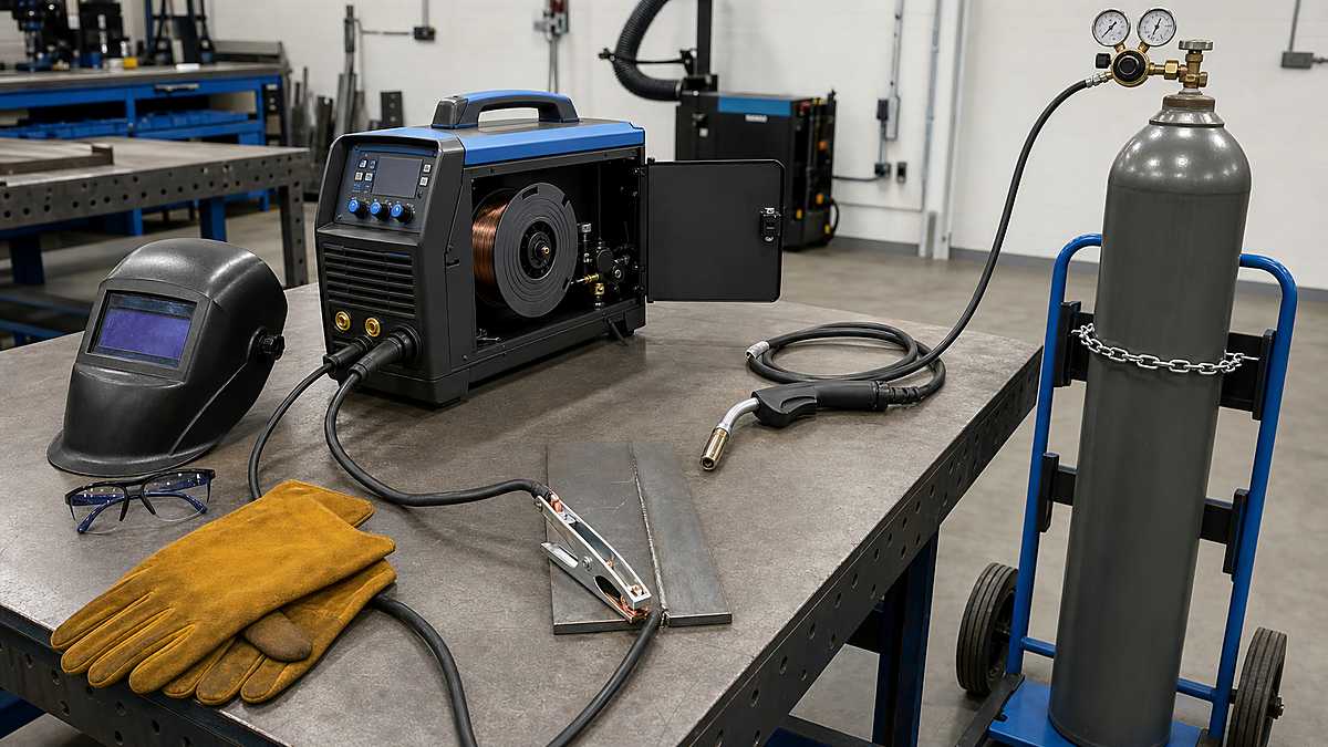
To set up a welding machine, first match the machine to the available input power and the process you plan to use. With the power switched off, inspect the equipment, connect the correct torch or holder and work lead, confirm polarity, install the right consumable, prepare shielding gas if required, clean the workpiece, and start from the machine chart or consumable data. Make the first weld on scrap, not on the finished part.
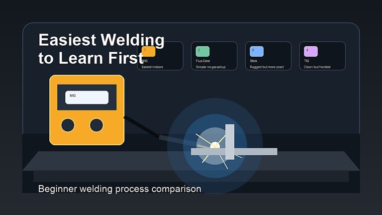
MIG, flux core, stick, and TIG share the same safety-first sequence, but their hardware and controls differ. MIG needs wire, drive rolls, a gun, and usually gas. Self-shielded flux core may run without gas. Stick uses a coated electrode. TIG uses a tungsten electrode, torch, shielding gas, and often a remote amperage control.
Mark Dawson beginner note: there is no universal polarity, gas flow, or amperage that fits every machine and consumable. Treat the owner’s manual, door chart, electrode package, and wire or tungsten data as the starting procedure.
Quick Welding Machine Setup Checklist
- Choose the welding process, material, joint, and consumable.
- Read the machine manual and verify input-power requirements.
- Prepare a dry, ventilated, fire-safe work area.
- Inspect the machine, plug, leads, gun or torch, holder, and work clamp.
- Switch the machine off before connecting or changing components.
- Connect the electrode-side lead and work lead for the required polarity.
- Install wire, rod, or tungsten that matches the process.
- Secure and connect shielding gas when the process requires it.
- Clean and clamp the workpiece; attach the work clamp to clean metal.
- Enter starter settings from the manual or chart.
- Put on complete PPE and perform a final area check.
- Test on matching scrap, inspect the bead, and adjust one variable at a time.
If you want to understand what happens after these connections are made, read How Does a Welding Machine Work?.
1. Choose the Process Before Connecting Anything
Start with the job, not the front-panel buttons. Identify the base metal, thickness, joint type, welding position, indoor or outdoor location, and required strength. Then choose a process and consumable that the machine actually supports.
| Process | Electrode | Shielding | Main Starter Controls |
|---|---|---|---|
| MIG/GMAW | Solid wire | External gas | Voltage and wire-feed speed |
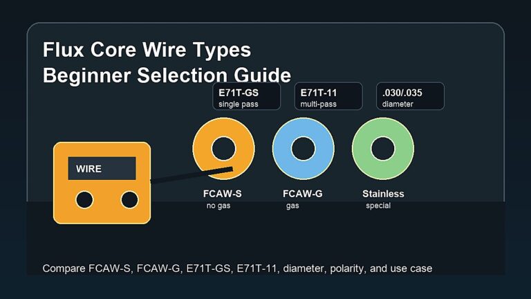
| Self-shielded FCAW | Flux-core wire | Flux in wire | Voltage and wire-feed speed |
| Gas-shielded FCAW | Flux-core wire | Flux plus external gas | Voltage and wire-feed speed |
| Stick/SMAW | Coated rod | Flux coating | Amperage, polarity, optional arc force |
| TIG/GTAW | Tungsten; separate filler when needed | External inert gas | Amperage, current type, gas, start mode |
A multi-process machine does not automatically include every accessory. Confirm that you have the correct gun, TIG torch, electrode holder, work lead, regulator, feeder parts, remote control, and gas connections for the selected mode.
2. Prepare a Safe Welding Area
Place the machine on a stable, dry surface with its air inlets and outlets clear. Keep it away from grinding dust, rain, standing water, and the direct path of sparks. Route cables so they are not crushed, cut, coiled tightly around hot work, or placed where people will trip over them.
Remove combustible material from the hot-work area and account for sparks that can pass through gaps or travel behind a bench. Provide suitable ventilation without blowing shielding gas away from the joint. Keep the correct fire extinguisher accessible and follow any workplace hot-work permit or fire-watch requirement.
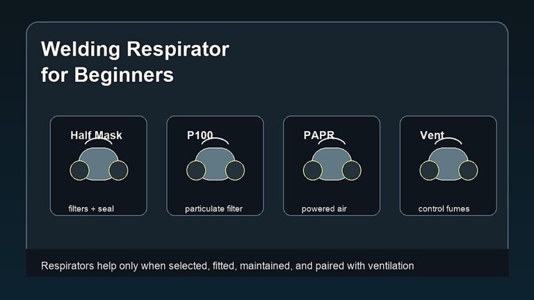
Wear safety glasses under a correctly shaded welding helmet, dry welding gloves, flame-resistant clothing, and suitable footwear. Build the full list from Welding Safety Equipment for Beginners.
3. Verify Input Power
Read the nameplate and manual for input voltage, phase, frequency, and maximum or rated input current. Some dual-voltage machines switch automatically; others need an internal or front-panel configuration. Never assume that a plug adapter changes the voltage available to the machine.
Use a properly installed receptacle, grounding system, conductors, and overcurrent protection. A qualified electrician should address new circuits, damaged outlets, uncertain wiring, or repeated breaker trips. If an extension cord is permitted, use the wire size and maximum length specified by the manufacturer. Undersized cords cause voltage drop and heating.
For generator power, check the welder’s required input and the generator guidance. Rated running watts alone may not describe voltage regulation, surge behavior, or compatibility with sensitive inverter electronics.
4. Inspect the Machine and Accessories
- Look for cracked cases, missing panels, blocked vents, liquid contamination, and loose hardware.
- Inspect the input cord and plug for cuts, exposed conductors, bent pins, heat damage, or makeshift repairs.
- Check welding leads for damaged insulation, loose lugs, overheated connectors, and undersized cable.
- Inspect the electrode holder, gun, torch, trigger, strain relief, work clamp, and gas hose.
- Confirm that contact tips, nozzles, cups, collets, drive rolls, and liners match the consumable.
- Do not use equipment that smells burned, trips protection repeatedly, or has damaged safety components.
Keep service panels closed during operation. Internal capacitors may retain dangerous voltage after the machine is unplugged, so internal diagnosis belongs to qualified service personnel.
5. Connect Leads and Confirm Polarity
Turn the machine off before changing output leads. Identify the electrode-side connection: MIG or flux-core gun, TIG torch, or stick electrode holder. The other lead is the work lead. On DC, the electrode-side lead connected to positive produces DCEP; connected to negative produces DCEN.
Do not choose polarity from process name alone. Solid-wire MIG commonly uses DCEP. Many self-shielded flux-core wires use DCEN, while many gas-shielded flux-core wires use DCEP, but the wire data controls. Stick polarity depends on the exact rod. Most DC TIG uses DCEN, while aluminum TIG commonly uses AC on an AC-capable machine.
Some wire welders change polarity through internal studs or a jumper. Follow the connection diagram inside the permitted user-access area. Review AC vs DC Welding when terminal labels or current type are unclear.
6. Attach the Work Clamp Correctly
Clamp to clean, bare metal on the workpiece or a conductive table that provides a known path. Paint, rust, mill scale, oil, loose jaws, or a distant connection can add resistance and destabilize the arc. Keep the clamp near the weld when practical.
Avoid routing current through bearings, hinges, chains, lifting devices, vehicle electronics, gas cylinders, or unknown building paths. The work clamp completes the welding circuit; protective earth grounding is a separate safety function.
7. Prepare the Metal and Test Coupon
Identify the material before grinding or welding. Remove oil and grease with an approved method before using abrasives. Clean rust, paint, oxide, plating, and mill scale as required by the process and procedure. Unknown coatings can release hazardous fumes; stop and identify them first.
Fit and clamp the joint so it cannot move when tacked. Prepare a scrap coupon of the same alloy and similar thickness. The coupon lets you verify polarity, arc behavior, heat, gas coverage, and bead shape without damaging the project.
MIG Welder Setup
- Choose wire and gas: match wire classification, diameter, shielding gas, and polarity to the material and transfer mode.
- Install the spool: orient it so wire feeds in the direction shown by the manual; set hub tension only high enough to prevent overrun.
- Fit the drive roll: use the correct groove type and size. Smooth V-grooves are common for solid steel wire; knurled rolls are commonly used for flux core; aluminum systems may require U-grooves and specialized feeding hardware.
- Thread the wire: remove sharp burrs, guide wire through the inlet and liner, close the pressure arm, and keep fingers away from drive rolls.
- Set drive-roll pressure: use enough pressure for reliable feeding without crushing or shaving the wire.
- Match tip and liner: install a contact tip for the wire diameter and verify nozzle condition.
- Connect gas: secure the cylinder upright, install the correct regulator or flowmeter, connect the hose, and check the system using the approved leak method.
- Set voltage and wire speed: start with the door chart for material, thickness, wire, and gas.
- Purge and test: confirm smooth wire feed and gas flow before making a test bead.
Excessive drive pressure damages wire and liner; too little causes slipping. Gas flow that is too high can create turbulence and draw air into the shield, while too little may leave the puddle exposed. Use Wire Feed Speed Calculator and Formula and Gas Flow Rate Calculator and Formula as reference tools, then follow the machine and consumable data.
Self-Shielded Flux-Core Setup
The wire-loading steps resemble MIG setup, but several details change. Confirm that the machine supports the wire diameter, install the recommended drive roll and contact tip, and set the exact polarity printed on the spool or data sheet. Many common self-shielded wires use DCEN, but that is not a universal rule.
Do not connect shielding gas to a self-shielded product unless its manufacturer specifically requires it. Expect slag, more smoke, and different technique than solid-wire MIG. Check that ventilation is adequate and that sparks will not reach combustibles.
Stick Welder Setup
- Choose an electrode classification and diameter suited to the material, position, joint, and machine output.
- Read the package for AC, DCEP, DCEN, storage, and amperage requirements.
- With power off, connect the holder and work lead for the specified polarity.
- Inspect the holder jaws and place a dry, undamaged rod securely in the holder.
- Set amperage from the electrode range, then account for position and test-coupon behavior.
- Start arc-force or dig near the machine’s recommended neutral setting unless the manual or procedure says otherwise.
- Place unused rods in storage appropriate to their classification instead of leaving them in damp conditions.
Polarity cannot be guessed from rod diameter. An E6010, E6011, E6013, and E7018 may have different current requirements, and products within a classification can differ. See How to Choose Welding Rod Size for selection basics.
TIG Welder Setup
- Connect the torch: fit the power, gas, and coolant connections required by the air- or water-cooled torch.
- Connect the work lead: verify the resulting polarity, not just the terminal color.
- Install the remote: connect a foot pedal or fingertip control if the procedure uses one.
- Secure the gas cylinder: install the correct regulator or flowmeter and approved hose, then check for leaks.
- Choose tungsten: match type and diameter to current type, amperage, and machine guidance.
- Prepare tungsten: use a dedicated grinding surface and the shape recommended for DC or AC operation.
- Assemble the torch: match collet, collet body or gas lens, cup, back cap, and tungsten size.
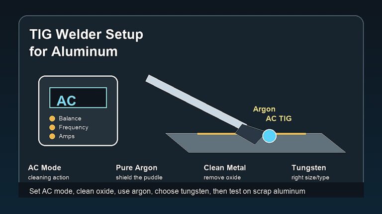
- Select output: DCEN is common for steel and stainless; AC is common for aluminum on suitable equipment.
- Set current and sequence: define maximum amperage, gas timing, start mode, and any pulse or AC controls from the manual.
- Clean filler and work: keep TIG materials free of oil, oxide, and cross-contamination.
Use Different Types of Tungsten for TIG Welding before selecting a color code or diameter. Gas, tungsten, cup, and current must work as one system.
8. Enter Starter Settings
Use the machine chart for the exact process, material, thickness, wire or rod diameter, and gas. If the machine has a synergic mode, verify that every selected input is correct; automation cannot recognize the wrong wire or polarity for you.
Write down the starting values. On MIG or flux core, note voltage and wire-feed speed. On stick or TIG, note amperage and current type. Add gas flow, pulse, inductance, arc force, preflow, postflow, or AC balance only when the process uses them.
9. Make and Read a Test Weld
Run a bead on the prepared coupon using the planned gun or torch angle, arc length, stickout, and travel speed. Watch and listen to the arc. Then inspect bead width, crown, toe tie-in, spatter, undercut, porosity, slag behavior, and visible penetration indicators appropriate to the joint.
Change one variable at a time so the result is understandable. If the arc is unstable, verify work connection, polarity, consumable, gas, and input power before chasing panel settings. Appearance alone does not qualify structural, pressure, vehicle, trailer, lifting, or other safety-critical work.
10. Safe Shutdown
- Finish the weld and allow postflow or burnback sequence to complete.
- Place the hot gun, torch, or holder where it cannot contact metal or damage hoses.
- Switch off the welding output and machine as directed.
- Close the shielding-gas cylinder valve when applicable.
- Release or manage downstream pressure according to the regulator and manufacturer instructions.
- Disconnect input power before approved maintenance, drive-roll changes, or internal user-service tasks.
- Mark hot metal, inspect the area for smoldering material, and maintain the required fire watch.
- Store dry consumables, coil cables loosely, and secure cylinders upright.
Common Setup Mistakes
- Choosing settings before identifying material thickness and consumable
- Confusing AC input power with AC welding output
- Using the wrong polarity for flux-core wire or stick electrode
- Clamping over paint, rust, or a weak table connection
- Installing the wrong drive-roll groove, liner, or contact-tip size
- Overtightening drive rolls until wire deforms
- Leaving a shielding-gas cylinder unsecured
- Using excessive gas flow to “fix” porosity
- Blocking machine cooling vents or exceeding duty cycle
- Testing the first settings on the finished project
- Welding unknown coatings or containers
- Opening service panels without qualified training and isolation procedures
Safety References
- Miller: MIG wire, gas, work clamp, and starter settings
- Miller: TIG torch, work clamp, polarity, remote, and tungsten setup
- Miller: TIG system components and shielding
- OSHA 1910.254: arc-welding equipment selection, installation, and instruction
- OSHA: hot-work inspection, PPE, fire protection, and ventilation
FAQ
What setting should a beginner welder start with?
Use the machine chart or manual for the exact material, thickness, process, and consumable. Test those values on matching scrap and adjust one variable at a time.
Where should the work clamp go?
Attach it to clean bare metal on the workpiece or a known conductive table, as close to the weld as practical, while preventing current from crossing sensitive components.
Does MIG use positive or negative polarity?
Solid-wire MIG commonly uses DCEP. Flux-core wire varies, so read the spool or data sheet. The machine’s internal jumper may also need repositioning.
Can I weld immediately after installing wire?
First verify drive-roll pressure, liner and tip size, polarity, gas, work connection, settings, PPE, and the work area. Feed and test the wire on scrap before touching the project.
How tight should MIG drive rolls be?
Only tight enough to feed wire consistently without slipping. Excess pressure can flatten, shave, or deform wire and overload the feeding system. Use the machine’s tension test.
Should the gas cylinder stay open between jobs?
No. Close the cylinder valve when the system is not in use and follow the regulator manufacturer’s shutdown procedure. Keep the cylinder secured upright during use and storage.
Final Setup Rule
A correct setup creates a known chain from input power to machine mode, output leads, polarity, consumable, shielding, work connection, material, and starter settings. If one link is unknown, stop and verify it before striking an arc.
Keep the first test on scrap, use the manual as the baseline, and make changes deliberately. That approach is slower than guessing for the first few minutes and much faster than troubleshooting a damaged liner, contaminated tungsten, porous weld, stuck rod, or unsafe electrical connection afterward.