Wire Feed Speed Calculator and Formula
A wire feed speed calculator and formula gives a starting MIG or flux-core feed rate in inches per minute (IPM) or meters per minute (m/min). For constant-voltage wire welding, feed speed strongly affects welding current because the power source must melt wire at the rate the feeder delivers it.
The useful starting number depends on wire diameter, filler type, target current, transfer mode, shielding method, contact-tip-to-work distance, polarity, and machine design. A calculator cannot replace the chart inside the welder, the filler data sheet, an approved WPS, or a test weld on matching scrap.
Mark Dawson beginner note: do not turn wire speed until the arc sounds right and ignore the bead. Watch fusion, penetration, bead shape, spatter, contact-tip behavior, and burn-through. Stable sound is helpful, but the weld must still meet the job requirement.
Quick Wire Feed Speed Calculator
A common mild-steel short-circuit starting method has two parts:
- Estimate starting current from material thickness.
- Multiply current by an approximate IPM-per-amp factor for the solid-wire diameter.
Starting amps ≈ material thickness in thousandths of an inch
Starting WFS in IPM ≈ target amps × wire factor
| Solid Steel Wire | Approx. IPM per Amp | Example at 100 A |
|---|---|---|
| 0.023/0.024 in | 3.5 | 350 IPM |
| 0.030 in | 2.0 | 200 IPM |
| 0.035 in | 1.6 | 160 IPM |
| 0.045 in | About 1.0 | About 100 IPM |
These are approximate mild-steel solid-wire factors reflected in Miller educational guidance. They are not universal for aluminum, stainless, metal-cored wire, self-shielded flux core, spray transfer, pulsed programs, or every power source.
Worked Example: 1/8-Inch Mild Steel
One-eighth inch equals 0.125 inch, or 125 thousandths. The simple rule suggests about 125 A as an initial current target for a single-pass mild-steel setup.
- With 0.030-inch wire: 125 × 2.0 = 250 IPM
- With 0.035-inch wire: 125 × 1.6 = 200 IPM
- With 0.024-inch wire: 125 × 3.5 = 438 IPM
The wire diameter changes the length that must be fed to deliver a similar metal volume and current range. Start with the machine chart when available, set the recommended voltage and gas, verify polarity, then make a test weld. The Welding Wire Size Chart explains where common diameters generally fit.
IPM and m/min Conversion
- m/min = IPM × 0.0254
- IPM = m/min × 39.37
- ft/min = IPM ÷ 12
| IPM | Approx. m/min | m/min | Approx. IPM |
|---|---|---|---|
| 100 | 2.54 | 3 | 118 |
| 150 | 3.81 | 5 | 197 |
| 200 | 5.08 | 7 | 276 |
| 250 | 6.35 | 9 | 354 |
| 300 | 7.62 | 12 | 472 |
| 400 | 10.16 | 15 | 591 |
Do not confuse IPM wire feed with IPM travel speed. Wire feed measures electrode entering the gun. Travel speed measures the torch moving along the joint.
Measure Actual Wire Feed Speed
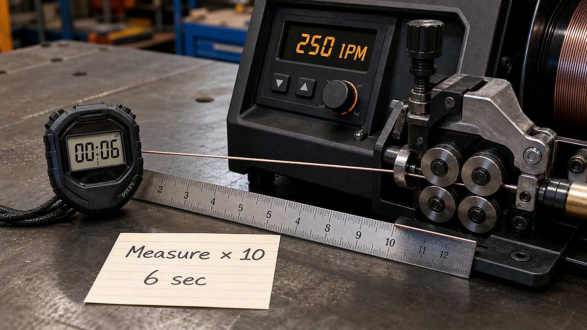
A numbered dial may not show true IPM, and a digital display can drift from actual delivery because of calibration, drive-roll slip, liner drag, or supply voltage. A cold-feed test checks the feeder without striking an arc.
- Follow the manual’s safe cold-inch or jog procedure.
- Keep wire away from the work clamp and conductive surfaces.
- Use a clean reference point at the contact tip.
- Feed wire for an accurately timed interval.
- Measure the straight wire length delivered.
- Apply the time multiplier to calculate IPM or m/min.
| Test Time | Imperial Formula | Metric Formula |
|---|---|---|
| 6 seconds | Measured inches × 10 | Measured meters × 10 |
| 15 seconds | Measured inches × 4 | Measured meters × 4 |
| 30 seconds | Measured inches × 2 | Measured meters × 2 |
| 60 seconds | Measured inches = IPM | Measured meters = m/min |
If 25 inches feeds in six seconds, actual speed is 25 × 10 = 250 IPM. If 0.7 meter feeds in six seconds, actual speed is 7 m/min, or about 276 IPM.
Calibrate a 1-10 or 1-100 Wire-Speed Dial
Some small welders show only a numbered knob. The number is a control position, not IPM. Build a simple calibration table with the cold-feed method instead of assuming position 5 means half of the machine’s maximum speed.
- Choose several dial positions across the usable range.
- Cold-feed for the same timed interval at each position.
- Measure delivered wire and calculate IPM.
- Repeat any reading that looks inconsistent.
- Record date, wire diameter, feeder, gun, and supply condition.
| Dial Position | 6-Second Length | Calculated WFS | Notes |
|---|---|---|---|
| 2 | 8 in | 80 IPM | Example only |
| 4 | 15 in | 150 IPM | Example only |
| 6 | 23 in | 230 IPM | Example only |
| 8 | 32 in | 320 IPM | Example only |
Do not copy the example values to another welder. Control response may be nonlinear, and measured speed can change after a liner, motor, control board, or drive system is serviced. Recheck when feed behavior changes.
Find a Machine-Specific IPM-per-Amp Factor
The published factors are convenient starting values. A production shop can develop a more relevant relationship from an approved test setup by measuring actual WFS and stable welding current.
Observed IPM-per-amp factor = measured WFS ÷ measured current
If a stable 0.035-inch solid-wire procedure measures 285 IPM and 178 A, the observed factor is 285 ÷ 178 = 1.60 IPM per amp. Record voltage, CTWD, gas, polarity, transfer mode, wire lot, and position with the result. Changing those variables can change the relationship.
Do not create a new procedure merely from this ratio. Use it to audit feeder displays, compare repeat setups, or estimate a test point inside the approved operating window.
Wire Length and Consumption Planning
WFS also tells you how much linear wire passes through the gun during arc time:
Wire length used = WFS × arc time
At 250 IPM for 18 arc minutes, the feeder delivers 4,500 inches, or 375 feet of wire. Linear length is not deposited weight. To estimate weight, use wire cross-sectional area, filler density, and deposition efficiency.
For a spool-life estimate, use the manufacturer’s wire weight per unit length or calculate solid-wire weight carefully. Flux-cored and metal-cored wires need product-specific linear weight because their cores do not have the density of solid steel.
Setup Worksheet: Thin Sheet
Suppose the machine chart recommends 0.023-inch wire for thin mild-steel sheet. Record the chart voltage, WFS, polarity, gas, joint, and position. Cold-feed the stated WFS and compare it with the display. Make short test welds while watching for burn-through, poor tie-in, and distortion.
A thin-sheet setup is sensitive to fit-up, travel speed, tack sequence, and heat accumulation. Do not compensate for a large gap by continuing to increase wire speed. Improve fit-up or use the repair method approved for the part.
Setup Worksheet: 3/16-Inch Mild Steel
Three-sixteenths inch equals 0.1875 inch, or about 188 thousandths. The simple current rule suggests roughly 188 A as an initial estimate. With 0.035-inch solid wire and the 1.6 factor:
188 × 1.6 ≈ 301 IPM
Before setting 301 IPM, check whether the machine chart, wire, transfer mode, input power, and joint support that current. The correct production value may differ because a fillet, groove, vertical weld, gap, or multi-pass joint does not behave like the simple thickness rule.
Keep a Repeatable WFS Log
A short setup log helps separate feeder problems from technique changes. Record displayed WFS, measured WFS, voltage, average current if available, CTWD, wire, gas, polarity, position, travel speed, and test result. Add the drive-roll groove, liner, and contact-tip size when troubleshooting.
If displayed speed remains 250 IPM but measured speed falls to 210 IPM, inspect the feed path before changing the procedure. If measured speed is correct but current changes, check CTWD, contact tip, work connection, voltage, and arc behavior.
Wire Feed Speed and Amperage
On a conventional constant-voltage GMAW system, increasing WFS generally increases current because more wire must be melted each second. Reducing WFS generally reduces current. The exact relationship depends on wire size, type, electrode extension, polarity, transfer mode, and power-source response.
This is why most MIG machines present voltage and wire feed as the main controls rather than a separate fixed amperage knob. Synergic systems may link controls internally, but the displayed program still depends on correct wire, gas, diameter, and process selection.
Wire Feed Speed and Voltage
Wire feed and voltage must be balanced. WFS supplies electrode and influences current. Voltage influences arc length and bead characteristics. Too much wire for the selected voltage can make the wire stub into the work. Too much voltage for the feed can create a long, unstable arc, excess spatter, or burn-back.
| Arc Behavior | Possible Cause | First Check |
|---|---|---|
| Wire repeatedly pushes gun back | WFS high for voltage or poor electrical connection | Verify chart, voltage, polarity, and work lead |
| Wire burns back to tip | WFS low, voltage high, or feed interruption | Check WFS, tip, liner, and drive system |
| Harsh spatter | Voltage/WFS mismatch or gas/polarity issue | Return to approved starting values |
| Cold raised bead | Low energy, fast travel, or poor technique | Inspect settings, fit-up, and fusion |
Wire Feed Speed and Deposition Rate
Higher feed speed moves more filler through the gun. For solid wire, theoretical deposition can be estimated from wire area, feed speed, density, and efficiency:
Deposition rate = wire area × WFS × density × time conversion × efficiency
Deposition is not a substitute for current or procedure limits. A calculated high feed rate may exceed the stable range of the process. Use the Weld Deposition Rate Calculator for lb/hr and kg/hr examples.
Solid Wire vs Flux-Cored Wire
The simple IPM-per-amp factors are for common solid steel wire starting estimates. Flux-cored products have a metal sheath and formulated core. Their burn-off behavior, polarity, operating range, contact-tip-to-work distance, and deposition efficiency come from the product data sheet.
Self-shielded and gas-shielded wires can require very different settings even at the same diameter. Use the Flux Core Welding hub and the exact wire manufacturer’s operating range rather than transferring a solid-wire factor.
Aluminum Wire Feed Speed
Aluminum has lower density and different electrical and feeding behavior than steel. It often uses higher WFS for a given current range, along with a spool gun or push-pull system, suitable liner, drive rolls, contact tip, argon, and transfer mode.
Do not use the steel thickness rule or steel wire factors as an aluminum setting. Start with the machine and filler charts. Soft aluminum wire can bird-nest or shave if tension and the feed path are wrong.
Contact-Tip-to-Work Distance
Changing electrode extension can change current at the same displayed WFS. A longer stickout adds electrical resistance and can reduce current while heating more wire before it reaches the arc. A shorter stickout can raise current and overheat the tip or gun if it falls outside the procedure.
Keep CTWD consistent while tuning and testing. A calculator assumes the setup stays within the operating range used to develop the chart or factor.
Why Actual Feed Speed Changes
- Drive-roll slip: wrong groove, tension, or contaminated wire.
- Liner drag: kinked, dirty, worn, or wrong-size liner.
- Tip restriction: damaged or incorrect contact tip.
- Spool brake: too tight causes drag; too loose causes overrun.
- Gun cable bends: tight coils increase resistance.
- Supply variation: some feeders change behavior under poor input power.
- Calibration error: displayed and measured WFS may differ.
Feeder Setup Checklist
- Confirm wire classification and diameter.
- Install the correct drive-roll type and groove.
- Use a liner and contact tip sized for the wire.
- Set spool brake only high enough to prevent overrun.
- Apply drive-roll pressure without crushing or deforming wire.
- Route the gun cable with gentle bends.
- Verify polarity and shielding setup.
- Measure actual cold-feed speed.
- Start from the welder or filler chart.
- Test on matching scrap and inspect the result.
Common Calculator Mistakes
- Using thickness as a guaranteed amperage: the rule is only a mild-steel starting estimate.
- Mixing IPM and m/min: 250 IPM equals 6.35 m/min, not 250 m/min.
- Using solid-wire factors for FCAW: follow product data.
- Ignoring voltage: WFS cannot be tuned alone.
- Trusting an uncalibrated dial: measure actual cold feed.
- Changing stickout while testing: current and arc behavior can shift.
- Chasing sound only: inspect bead profile and fusion.
WFS and Welding Defects
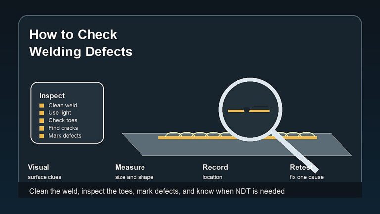
Incorrect feed speed can contribute to spatter, burn-back, stubbing, poor starts, burn-through, or lack of fusion, but it is rarely the only possible cause. Gas coverage, polarity, voltage, travel speed, angle, CTWD, fit-up, contamination, and electrical connections also matter.
Use the Welding Defects hub to identify symptoms, then change one controlled variable at a time. Do not cover a gas leak or dirty joint by increasing WFS.
Safety Notes
Cold-feed wire can puncture skin or eyes and may emerge unexpectedly from the contact tip. Keep the gun pointed away from people, disconnect or isolate output as the manual requires, wear safety glasses, and keep hands away from drive rolls and pinch points.
Live welding adds electric shock, fire, fumes, UV radiation, burns, compressed gas, and hot-metal hazards. Review Welding Safety Equipment, Miller’s MIG parameter guidance, the Miller MIG handbook, Lincoln Electric feeder guidance, and OSHA welding hazards.
FAQ
How do I calculate MIG wire feed speed?
For a mild-steel starting estimate, calculate approximate amps from thickness and multiply by the solid-wire IPM-per-amp factor. Use the machine chart and test weld as the final starting authority.
How do I check actual IPM?
Cold-feed wire for six seconds, measure the inches delivered, and multiply by ten. Follow the machine’s safe jog procedure and keep wire away from people and conductive surfaces.
How many IPM is 10 m/min?
Multiply 10 by 39.37. The result is approximately 394 IPM.
Does wire feed speed control amperage?
In constant-voltage MIG and flux-core welding, WFS strongly influences the resulting current. The exact relationship depends on wire, extension, process, and power source.
Why does the wire keep stubbing into the work?
WFS may be high for the selected voltage, but also check polarity, work connection, contact tip, liner, gas, stickout, and machine chart.
Can I use the same WFS for solid wire and flux core?
Not automatically. Use the exact wire manufacturer’s operating range because construction, polarity, shielding, extension, and burn-off behavior differ.
Final Advice
A wire feed speed calculator and formula provide a sensible test value, not a finished procedure. Use the correct factor and units, verify actual feeder output, and balance WFS with voltage, CTWD, gas, polarity, and wire data.
Once the arc is stable, inspect the weld rather than trusting the display alone. Consistent measurement and one-variable-at-a-time adjustment produce more reliable settings than guessing from sound.