Gas Flow Rate Calculator and Formula
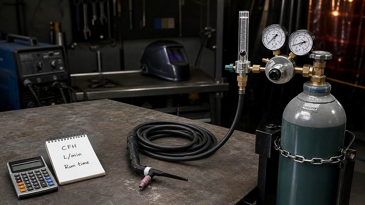
A gas flow rate calculator and formula can answer several practical welding questions: how much shielding gas a job will use, how long a cylinder may last, how to convert CFH to L/min, and what the gas may cost. The arithmetic is simple once the units and the type of time are clear.
The important number for MIG and TIG shielding is flow, not cylinder pressure. In the United States, flowmeters commonly show cubic feet per hour, or CFH. Metric flowmeters commonly show liters per minute, or L/min. Cylinder capacity, actual trigger time, TIG pre-flow and post-flow, purge gas, leaks, and shop drafts all affect the final result.
Mark Dawson beginner note: treat every calculated setting as a planning value. Set and verify gas while it is flowing, follow the welder and consumable instructions, and make a test weld. Turning the flow higher does not automatically improve shielding.
Quick Gas Flow Calculator
Use the formula that matches the answer you need. Keep CFH with hours and L/min with minutes. Mixing those units is the most common reason a result is off by a factor of 60.
| What You Need | Formula | Result Unit |
|---|---|---|
| Gas used | Flow rate × gas-on time | ft³ or liters |
| Cylinder run time | Usable cylinder volume ÷ flow rate | Hours or minutes |
| Average flow rate | Gas volume used ÷ gas-on time | CFH or L/min |
| Gas cost | Gas used × cost per volume | Currency |
| Gas per weld length | Flow rate ÷ travel speed | Volume per length |
Example: a MIG gun flowing 25 CFH for 1.5 hours of total trigger time uses approximately 37.5 cubic feet of shielding gas. The calculation is 25 × 1.5 = 37.5 ft³. It does not mean the welder must finish the job in 1.5 clock hours; fitting, tacking, brushing, and repositioning happen while the gas is off.
Gas Flow Rate Formula
The general volume-flow relationship is:
Flow rate = gas volume ÷ elapsed gas-flow time
If 30 cubic feet of gas passes through a system during 1.5 hours, the average rate is 30 ÷ 1.5 = 20 CFH. If 180 liters pass in 12 minutes, the average rate is 180 ÷ 12 = 15 L/min.
This formula needs measured gas volume and measured time. A pressure reading alone is not enough because pressure and flow describe different things. For the orifice, regulator, and pressure-drop issue, see Calculate Gas Flow Rate from Pressure Measurement.
CFH and L/min Conversion
Many welders compare a U.S. machine chart with a metric flowmeter. These rounded conversions are accurate enough for normal planning:
- L/min = CFH × 0.472
- CFH = L/min × 2.119
- CFM = CFH ÷ 60
- CFH = CFM × 60
| CFH | Approx. L/min | L/min | Approx. CFH |
|---|---|---|---|
| 10 | 4.7 | 5 | 10.6 |
| 15 | 7.1 | 8 | 16.9 |
| 20 | 9.4 | 10 | 21.2 |
| 25 | 11.8 | 12 | 25.4 |
| 30 | 14.2 | 15 | 31.8 |
| 40 | 18.9 | 20 | 42.4 |
Do not confuse CFH with CFM. A setting of 20 CFM would equal 1,200 CFH, far beyond a normal small-shop shielding gas setting. Read the letters on the flowmeter before adjusting it.
Welding Gas Consumption Formula
For a job estimate, calculate gas-on time first. Then multiply by the selected flow rate.
Gas consumption in ft³ = flow in CFH × gas-on hours
Gas consumption in liters = flow in L/min × gas-on minutes
Suppose a TIG job has 52 minutes of arc time. Pre-flow and post-flow add an estimated 18 minutes, so planned gas-on time is 70 minutes. At 12 L/min, estimated consumption is 12 × 70 = 840 liters. Add a reasonable job allowance for test starts, purging, setup, and small losses instead of pretending the estimate is exact.
Cylinder Run-Time Formula
When the cylinder capacity is listed in cubic feet and the flowmeter uses CFH:
Run time in hours = usable cylinder capacity in ft³ ÷ flow in CFH
An 80 ft³ cylinder at 20 CFH has a theoretical gas-flow time of 4 hours. Real service can be shorter because of residual pressure, pre-flow, post-flow, purging, leaks, repeated starts, and variation in the flow setting. This is continuous gas-on time, not total hours spent in the shop.
| Cylinder Capacity | 15 CFH | 20 CFH | 25 CFH | 30 CFH |
|---|---|---|---|---|
| 40 ft³ | 2.7 hr | 2.0 hr | 1.6 hr | 1.3 hr |
| 80 ft³ | 5.3 hr | 4.0 hr | 3.2 hr | 2.7 hr |
| 125 ft³ | 8.3 hr | 6.3 hr | 5.0 hr | 4.2 hr |
| 150 ft³ | 10.0 hr | 7.5 hr | 6.0 hr | 5.0 hr |
| 250 ft³ | 16.7 hr | 12.5 hr | 10.0 hr | 8.3 hr |
Cylinder labels and naming conventions vary by supplier, so calculate from the supplier’s stated capacity rather than relying only on a letter or nickname. Compare common capacities in the Welding Tank Size Chart.
How to Estimate Gas Cost
First calculate the cost per cubic foot:
Cost per ft³ = refill or exchange price ÷ usable cylinder capacity
Then calculate the estimated job cost:
Job gas cost = estimated gas used × cost per ft³
If a 125 ft³ refill costs $55, the simple gas-only rate is $55 ÷ 125 = $0.44 per ft³. A job expected to use 42 ft³ has an estimated gas charge of $18.48. Cylinder rental, delivery, hazmat charges, taxes, downtime, and purge gas may need separate lines in a business estimate.
Estimate Shielding Gas by Weld Length
Production planning sometimes starts with weld length and travel speed. Convert the flow and travel units so their time basis matches.
Volume used for each foot = CFH ÷ travel speed in feet per hour
Volume used for each meter = L/min ÷ travel speed in meters per minute
At 20 CFH and a travel speed of 12 inches per minute, the torch moves 60 feet per hour. Gas per foot during arc-on travel is 20 ÷ 60 = 0.33 ft³ per foot. This excludes starts, stops, post-flow, tack welds, repairs, and operator delays.
Project Calculator Worksheet
A useful estimate keeps each input separate. Write down the process, gas, planned flow, weld length, travel speed, number of starts, pre-flow, post-flow, purge volume, cylinder capacity, and refill price. When the result looks wrong, separate inputs make the error easier to find.
| Input | Example | Why It Matters |
|---|---|---|
| Flow setting | 22 CFH | Base volume used while gas is on |
| Arc-on time | 75 minutes | Convert to 1.25 hours for CFH |
| Extra gas time | 15 minutes | Starts, pre-flow, and post-flow |
| Planning allowance | 10% | Setup variation and minor losses |
| Cylinder capacity | 125 ft³ | Used to estimate cylinder share |
| Refill price | $55 | Used to estimate gas-only cost |
In this example, total gas-on time is 90 minutes, or 1.5 hours. Base use is 22 × 1.5 = 33 ft³. A 10% allowance adds 3.3 ft³, giving 36.3 ft³. That is about 29% of a 125 ft³ cylinder. At $0.44 per ft³, the estimated gas-only cost is $15.97.
Use an allowance that reflects the job instead of applying the same percentage everywhere. A long automated weld with few starts may track the base formula closely. A TIG repair with many stops, long post-flow, and repeated test fits can use noticeably more gas outside the arc.
TIG Pre-Flow and Post-Flow Calculation
TIG gas use can be underestimated when only arc time is counted. For repeated short welds, calculate the non-arc gas time:
Extra gas minutes = number of starts × (pre-flow seconds + post-flow seconds) ÷ 60
Consider 60 tack welds with 0.5 second of pre-flow and 8 seconds of post-flow. Extra time is 60 × 8.5 ÷ 60 = 8.5 minutes. At 12 L/min, those starts use about 102 liters beyond the gas consumed during the arc itself.
Do not shorten post-flow only to save gas. The setting helps protect the hot tungsten and the cooling weld area. Use the torch and machine guidance, then improve planning by reducing unnecessary trigger pulls, fixing leaks, and organizing the work.
Back-Purge Gas Estimate
Back purging stainless or reactive material is a separate calculation from torch shielding. A simple plan includes the enclosed volume, the number of volume changes needed before welding, and the continuing purge flow during the weld.
Initial purge volume = enclosed space volume × planned volume changes
Total purge gas = initial purge volume + continuing purge flow × purge time
The required exchange rate and oxygen level depend on the material, joint, procedure, and quality requirement. Flow that is too high can create turbulence or pressure problems inside the joint. Use a proven procedure, suitable dams and vents, and an oxygen analyzer where the work requires measured purge quality.
Check a Calculator Result Before Using It
- Check that time units match the flow unit.
- Compare the selected flow with the machine or consumable guidance.
- Confirm cylinder capacity is stated as usable gas volume, not water volume or pressure.
- Make sure TIG post-flow and any purge stream are included.
- Compare the result with a simple cylinder runtime calculation.
- Record actual cylinder use after the job and refine the next estimate.
As a quick reasonableness check, a calculated project use of 200 ft³ cannot come from an 80 ft³ cylinder without a refill. Likewise, an 80 ft³ cylinder at 20 CFH cannot provide 20 continuous gas-on hours. Simple cross-checks catch unit errors before they affect a quote or leave a job short of gas.
Typical Starting Flow Ranges
There is no universal flow setting. Process, gas density, nozzle or cup size, gas lens, amperage, transfer mode, joint access, torch angle, stickout, and air movement matter. Use these values only as broad indoor starting points, then follow the machine, torch, consumable, or procedure instructions.
| Application | Broad Starting Range | Adjustment Factors |
|---|---|---|
| MIG short-circuit indoors | About 20-30 CFH | Nozzle size, gas mix, drafts |
| TIG with a standard cup | About 10-20 CFH | Cup size, tungsten stickout |
| TIG with a larger gas lens | Follow cup guidance | Lens and cup design change coverage |
| Gas-shielded flux core | Often higher than light MIG | Wire data sheet and nozzle size |
| Outdoor gas-shielded welding | Unreliable in wind | Use screens or a suitable process |
For process-specific gas selection, read What Gas Do You Use for TIG Welding?. If the work is outside, review Can You MIG Weld Outdoors? before compensating for wind by simply raising flow.
Why Actual Gas Use Is Higher
- Pre-flow and post-flow: TIG may flow gas before ignition and after the arc stops.
- Starts and test bursts: each trigger pull uses gas even when no useful weld length is produced.
- Purge gas: stainless pipe or enclosed work can use a separate purge volume.
- Leaks: loose fittings, damaged O-rings, cracked hoses, and solenoid problems waste gas.
- Excessive flow: a high setting increases cost and may create turbulent shielding.
- Unused cylinder volume: a shop may exchange a cylinder before every rated cubic foot is available.
A practical estimate can add a project allowance after the base calculation. Do not hide a large unexplained percentage inside the flow rate. Keep base gas use, purge use, and allowance visible so the estimate can be checked later.
How to Check the Flow at the Torch
- Secure the cylinder upright and identify the gas.
- Inspect the regulator, flowmeter, hoses, and fittings.
- Open the cylinder according to the supplier and equipment instructions.
- Trigger gas flow through the gun or torch.
- Read the flowmeter while gas is moving.
- Use a nozzle flow tester if regulator flow and weld behavior do not agree.
- Check the nozzle, diffuser, cup, gas lens, O-rings, and hose for restrictions or leaks.
- Make a test weld and inspect the shielding result.
Flow should be checked under operating conditions. Static cylinder pressure cannot prove that the correct volume reaches the weld. Porosity may also come from dirty metal, moisture, an incorrect gas, long stickout, poor torch angle, or a damaged gas path.
Common Calculator Mistakes
- Mixing minutes and hours: CFH requires hours; L/min requires minutes.
- Using shop time as gas time: gas is normally off during much of the fitting and cleaning work.
- Ignoring TIG post-flow: short welds with long post-flow can use more gas than arc time suggests.
- Calling CFH “pressure”: CFH is flow; PSI is pressure.
- Trusting cylinder names: verify actual rated capacity with the supplier.
- Assuming more flow is safer: excessive flow can waste gas and disturb shielding.
- Skipping a leak test: the formula cannot account for an unknown leak.
Shielding Gas Safety
Compressed gas cylinders store substantial energy. Keep cylinders upright and secured, protect valves during handling, use a regulator intended for the gas and pressure, and keep damaged pressure equipment out of service. Never use cylinder pressure as a reason to improvise fittings or repair a regulator.
Argon, carbon dioxide, helium, and shielding mixtures can displace oxygen. A gas that is not toxic can still create an asphyxiation hazard in a pit, tank, small room, or other poorly ventilated space. Welding also adds fumes, UV radiation, burns, electric shock, and fire risk. Review Welding Safety Equipment, OSHA welding hazard guidance, OSHA compressed gas information, and AWS free safety resources.
FAQ
How do you calculate welding gas flow rate?
Divide measured gas volume by the time gas was flowing. Use cubic feet and hours for CFH, or liters and minutes for L/min. For normal welding setup, read a suitable flowmeter while gas is moving.
How do you calculate how long a welding gas cylinder will last?
Divide usable cylinder capacity by flow rate. An 80 ft³ cylinder at 20 CFH gives about four theoretical gas-on hours. Leaks, purge gas, pre-flow, and post-flow reduce real service time.
How many L/min is 20 CFH?
Multiply 20 by 0.472. The result is approximately 9.4 L/min.
How many CFH is 15 L/min?
Multiply 15 by 2.119. The result is approximately 31.8 CFH.
Can I calculate CFH from cylinder PSI?
Not from one PSI reading alone. Flow also depends on the regulator, pressure drop, restriction, gas, temperature, and equipment calibration. Use a flowmeter or a manufacturer-specific conversion method.
Does higher gas flow prevent porosity?
Not always. Low flow can expose the weld pool, but excessive flow may become turbulent and draw surrounding air into the shielding zone. Check leaks, drafts, nozzle condition, gas type, and technique before raising flow.
Final Calculation Checklist
- Use CFH with hours or L/min with minutes.
- Separate arc time, pre/post-flow time, and purge time.
- Calculate theoretical use before adding a visible allowance.
- Verify cylinder capacity and refill cost with the supplier.
- Measure flow while gas is moving.
- Follow the machine, torch, consumable, and procedure guidance.
- Test the setup on scrap and correct leaks before welding the job.
The gas flow rate calculator and formula provide a solid planning estimate, but the weld still decides whether shielding is adequate. Keep the units consistent, verify actual flow at the torch, and treat safety and equipment instructions as the final authority.